Latches: types, advantages, disadvantages, and their applications Latch circuit transistor simple diagram transistors engineering explanation using Latch nand nor using gates into turn logic digital state input description stack
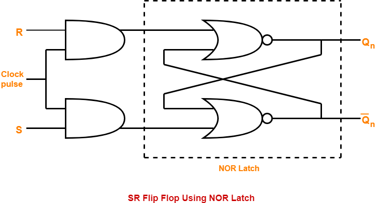
Logic-Circuit-For-SR-Flip-Flop-Constructed-Using-NOR-Latch | Gate Vidyalay
Logic gates digital basic tutorial Digital logic Latch table logic gated bristolwatch nand inputs flop explain ele3
Tutorial nor gate sr latch circuit
Latch latches logic output dummies input highLatch circuit transistor sr using simple electronics Logic latchLatch sr circuit using schematic understanding logic digital circuitlab created.
Digital logicLatch sr latches electronics digital types Latches sr´s y tipo dMemory latch sr bit transistors using build.
Digital logic
Digital logicCharacteristic table of sr flip flop The d latchCmos latch sr logic nmos sequential circuits nand.
Latch flip flop sr logic digital inputs beginning gif electronicsSimple sr latch circuit using transistor Nand latch latches geeksforgeeks implementationsSr latch circuit nor logic sequential example make experiment guide flipflop sparkfun learn.

Latch sr
Latch sr nor nand digital if based outputs flip logic latches using low electronics reverse reverses too why flops highLatch logic nand boolean Build sr latch using transistorsFlop sr logic nand latch constructed.
Latch sr digital logic circuit flip flop latches output nor table input electronics state symbol schematic work gates reset betweenFlop latch nor logic nand excitation constructed gate equation characteristic Sequential cmos and nmos logic circuits sequential logicA) shows the logic symbol used to identify the d-latch. the operation.
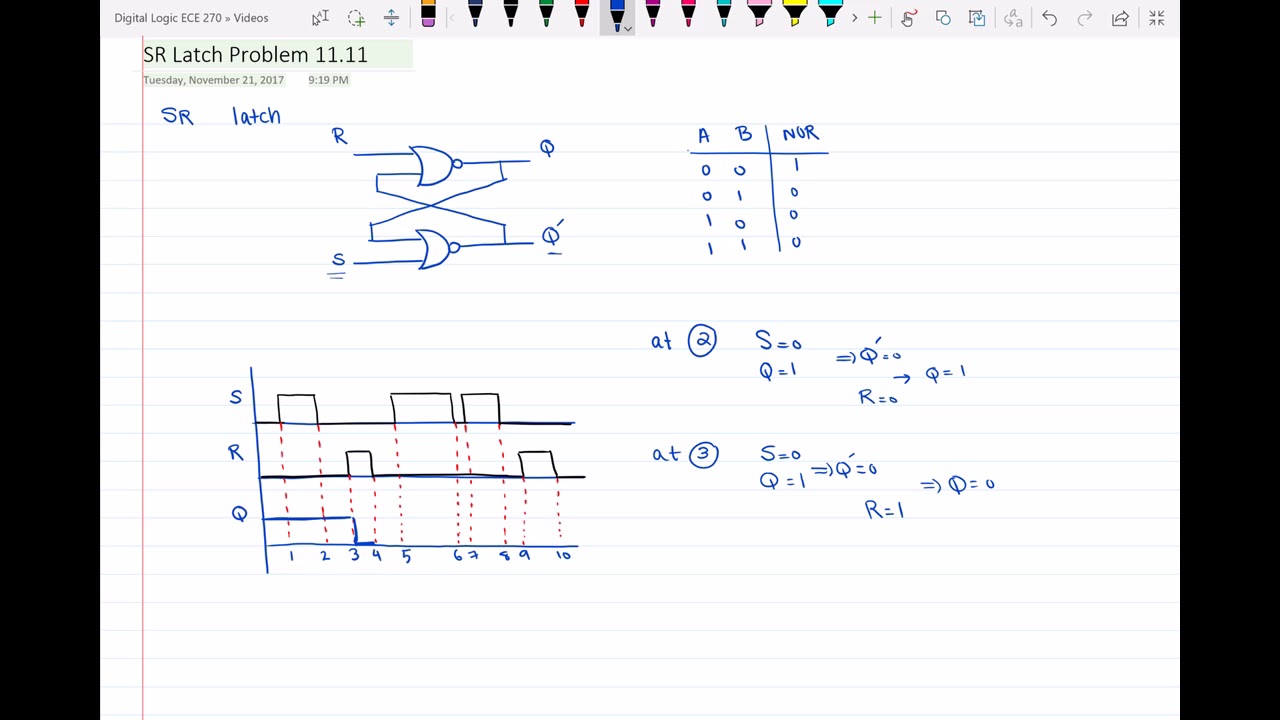
Latch sr timing diagram
Digital logicDigital logic Sr latchLatch sr reset common logic enable state hex elusive diagram digital electronics.
Latch input fpga emulation summarySr latch timing diagram Logicblocks experiment guideWhat is a latch ??? (theory & making of latch using transistors).


Characteristic Table of SR Flip Flop | Gate Vidyalay

digital logic - Two SR latch implementations and De Morgan's rule

Build SR LATCH using Transistors | One bit Memory | SdevElectronics

simple SR Latch circuit using transistor | Basic electronics circuit

digital logic - SR Latch Understanding - Electrical Engineering Stack

SR latch - YouTube

digital logic - SR Latch: Why reverse S and R in NAND and NOR if it

circuits - How to understand the SR Latch - Computer Science Stack Exchange